Recent posts
#51
Amplificadores / Re: Seletor 110/220 automátic...
Last post by bossman - 13 de May de 2026, as 13:26:54Quote from: xformer on 13 de May de 2026, as 13:10:43
O desenho foi feito pelo tal do Paulo Costa, citado pelo professor Bairros.
Paulo Costa foi este que criou o tópico :D
#52
Amplificadores / Re: Seletor 110/220 automátic...
Last post by xformer - 13 de May de 2026, as 13:10:43Um detalhe no esquema: os símbolos usados no MRC100 estão errados. O MRC100 como dito no vídeo, é um SCR ou retificador controlado de silício e o símbolo em questão é de um PUT (transístor unijunção programável) que é outro dispositivo. O símbolo do SCR tem o gate ligado no traço do cátodo e não no ânodo. O desenho foi feito pelo tal do Paulo Costa, citado pelo professor Bairros.
Eu sou inscrito no canal do professor Bairros e gosto muito das explicações dele, mas inevitavelmente, aparecem ocasionalmente alguns deslizes.
Eu sou inscrito no canal do professor Bairros e gosto muito das explicações dele, mas inevitavelmente, aparecem ocasionalmente alguns deslizes.
#53
Amplificadores / Seletor 110/220 automático am...
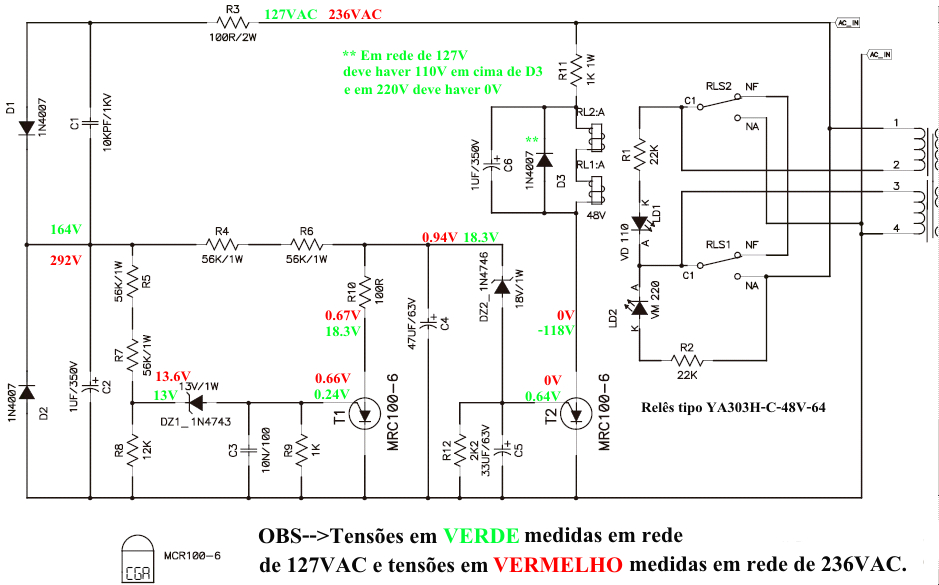
Last post by pcrock - 12 de May de 2026, as 22:06:22Olá amigos, hoje quero compartilhar com vocês um circuito muito interessante que é utilizado nos amplificadores Leac´s.
Trata-se do seletor de tensão automático para 110v/220v que equipa muitos de seus modelos.
Sempre me interessei por esse assunto e decidi medir tudo e estudar tudo sobre esse circuito para entender certinho como funcionava, pois esse modelo funciona muito bem!
Vou postar o esquema elétrico aqui e também deixar a explicação detalhada de seu funcionamento.
Esse circuito é muito bom, pois não usa nem transformador e nem resistores de potencia, que são grandes e esquentam demais! Bem diferente da enorme maioria dos circuitos similares.
Abaixo segue o esquema e quem quiser saber mais sobre a análise, deixo o link do vídeo do Excelentíssimo Professor Bairros, que fez uma análise irretocável mediante o esquema e sugestão que enviei a ele. Para quem não o conhece, vale se inscrever em seu canal, que na minha opinião, é o melhor canal brasileiro de eletrônica no Youtube.
Espero que gostem.
OBS--> Oesquema mostra o simbolo do que seriam PUTs ao invés de SCRs, isso se deve, provavelmente, a um erro gráfico mas, na realidade, são mesmo SCRs! Possuo o amplificador que usa esse circuito e pude confirmar na placa que o correto é SCR mesmo e não PUT.
Esquema:
Vídeo Professor Bairros com excelente análise e explicação
https://www.youtube.com/watch?v=WldXxi7T1F8&t=13s
#54
Conhecimento / Re: Artigos interessantes do H...
Last post by xformer - 12 de May de 2026, as 16:03:08 #55
Amplificadores / Re: Speaker Out em cubo
Last post by Doug - 08 de May de 2026, as 22:51:33Não sei se direto seria uma boa por causa da possivel flutuação na saída, a impedancia na saída do amplificador será alterada dependendo do que está ligado na outra ponta do line e no caso de alguma falha pode fritar tudo (um curto no cabo, por exemplo), acredito que um arranjo inserindo resistores ao conectar o jack dê mais estabilidade e segurança, algo como derivar o line através de um divisor de tensão na saída, por exemplo.
-----
me corrigindo aqui, eu li o Speaker out mas fiquei o tempo inteiro pensando num Line out, para ligar numa mesa e etc, mas para uma saída simples de falante para usar caixas externas é exatamente o que o Ruy falou, corta o polo positivo do cabo do falante e coloca um Jack com chave NF nele, conectou o cabo a chave abre, desconecta o falante interno e direciona o sinal para o cabo inserido.
-----
Quote from: Doug on 08 de May de 2026, as 22:51:33
Não sei se direto seria uma boa por causa da possivel flutuação na saída, a impedancia na saída do amplificador será alterada dependendo do que está ligado na outra ponta do line e no caso de alguma falha pode fritar tudo (um curto no cabo, por exemplo), acredito que um arranjo inserindo resistores ao conectar o jack dê mais estabilidade e segurança, algo como derivar o line através de um divisor de tensão na saída, por exemplo.
me corrigindo aqui, eu li o Speaker out mas fiquei o tempo inteiro pensando num Line out, para ligar numa mesa e etc, mas para uma saída simples de falante para usar caixas externas é exatamente o que o Ruy falou, corta o polo positivo do cabo do falante e coloca um Jack com chave NF nele, conectou o cabo a chave abre, desconecta o falante interno e direciona o sinal para o cabo inserido.
#56
Amplificadores / Re: Speaker Out em cubo
Last post by RuyThonson - 08 de May de 2026, as 00:49:54Boa noite.
Me desculpem a simplicidade da ideia. Mas eu faria bem simples.
Cortaria o cabo do falante e ligaria um jack chaveado. Se houver espaço no chassi do amp, bom. Mas se não houver, coloca nunca carcaça plástica pra organizar e prende em algum lugar legal.
Se alguém souber algum motivo pra isso não funcionar, por favor me explica que aproveito pra aprender.
Link do jack que estou sugerindo:
https://www.multcomercial.com.br/jack-j10-mono-6-35mm-com-4-terminais-ls-2028.html
#57
Amplificadores / Re: Speaker Out em cubo
Last post by Doug - 06 de May de 2026, as 21:20:24Como sugerido, vá direto na fonte:
http://www.handmades.com.br/forum/index.php?topic=1447.0
esse é o amplificador de onde a marca nacional tirou o Atomic e o Nitrous (nas versões de baixa potencia)
é só copiar o modelo original da saída de fone, ela se comporta exatamente assim, originalmente o Line out não desativa o falante interno.
#58
Amplificadores / Re: Speaker Out em cubo
Last post by xformer - 06 de May de 2026, as 13:25:10Procura o esquema elétrico do Atomic Drive 20 ADR, que tem a ligação do jack de alto-falante externo.
#59
Amplificadores / Speaker Out em cubo
Last post by guikusch - 06 de May de 2026, as 11:31:22Saudações. Alguém poderia me explicar como fazer a ligação de um Jack speaker out num cubo? Um amigo pediu pra fazer no atomic drive dele, mas pediu para que mantivesse a ligação original do falante, e quando conectar o cabo no Speaker out cortar o sinal que iria para o falante original.
#60
Luthieria / Suporte para plaina
Last post by Jimi - 05 de May de 2026, as 11:11:01Acabo de ver no Instagram e parece ser bem prático o suporte para trabalhos em madeira.
https://www.instagram.com/reels/DXmHDqWEQt0/
https://www.instagram.com/reels/DXmHDqWEQt0/